
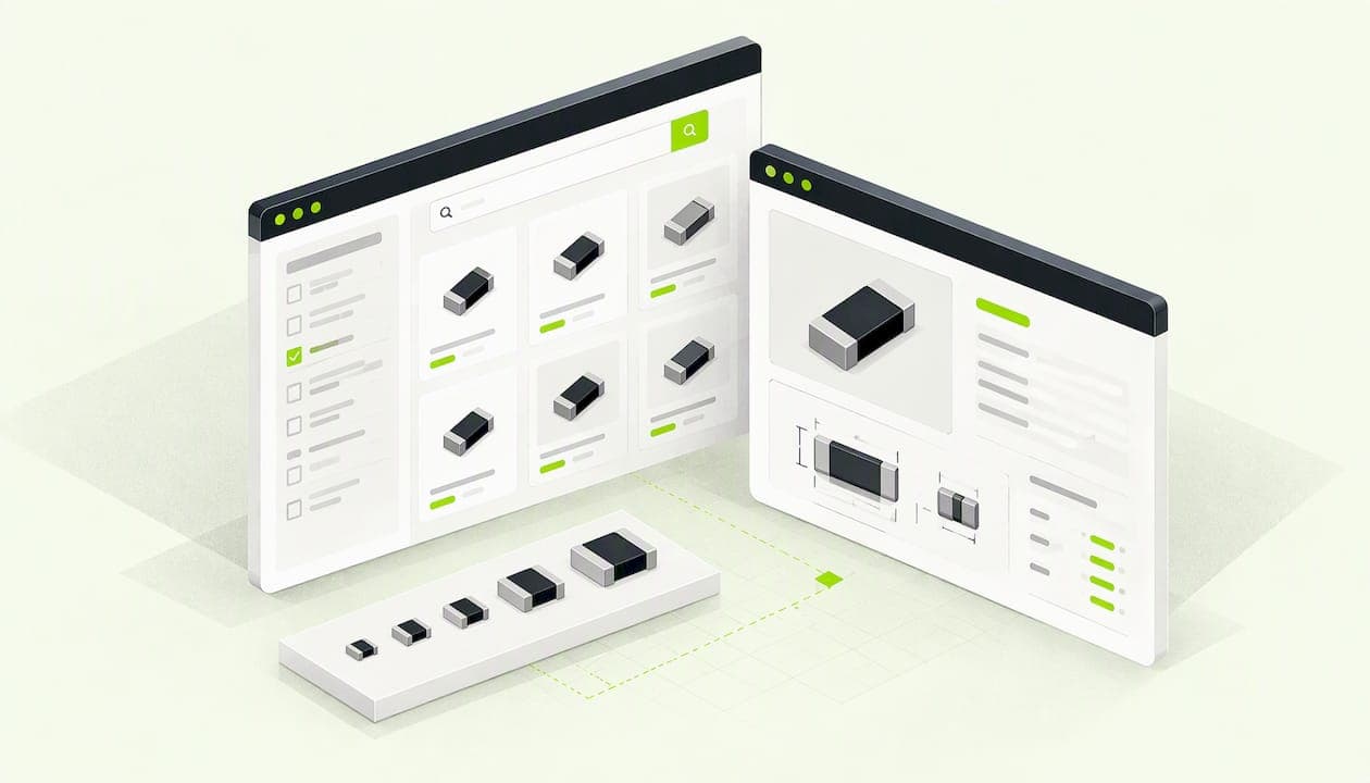
An SMD resistor size is a four-digit code that gives the part's length and width. In the US catalog convention it is read in hundredths of an inch, so a 0603 is roughly 0.060 × 0.030 in (1.6 × 0.8 mm). The common sizes are 0402, 0603, 0805 and 1206. Smaller sizes save board space but are harder to solder and handle less power. Below you get the code system, a size chart, head-to-head comparisons of 0402 vs 0603 and 0603 vs 0805, and a short checklist for picking a package.
TL;DR
- Imperial codes (0402, 0603, 0805) are length and width in hundredths of an inch. Metric codes (1005, 1608, 2012) are in tenths of a millimeter. The same four digits can mean different parts in each system.
- Nominal sizes: 0402 is 1.0 × 0.5 mm, 0603 is 1.6 × 0.8 mm, 0805 is 2.0 × 1.25 mm.
- Typical power ratings run about 0.063 W (0402), 0.1 W (0603) and 0.125 W (0805), but the series on the datasheet decides the real number.
- For hand assembly, 0603 is the practical floor. 0805 is easier still. 0402 usually calls for a microscope or a pick-and-place line.
- The code never gives thickness or the PCB land pattern. Take both from the manufacturer's datasheet.
Table of Contents
- What the four-digit code means
- SMD resistor size chart
- Body size is not footprint size
- 0402 vs 0603
- 0603 vs 0805
- What else to check before you choose
- Our perspective: size is a sourcing decision as much as a layout one
- Check sizes and stock on your real design
- Quick reference by use case
- FAQ
- Sources
What the four-digit code means
A chip resistor's size code describes its outline from above: length and width. It says nothing about thickness, which the SMT nomenclature guide says must come from the component manufacturer's datasheet.
In the imperial system, the digits are approximate dimensions in hundredths of an inch. Engineering LibreTexts puts imperial 0402 at about 0.039 × 0.020 in and 0603 at 0.063 × 0.031 in. That is why you will see 0603 described as 0.06 × 0.03 in: EEPower rounds it that way.
The metric system works the same way with different units: the digits are length and width in tenths of a millimeter. Imperial 0603 becomes metric 1608, meaning 1.6 × 0.8 mm.
Imperial vs metric: the trap
The trouble is that both systems reuse the same digits. KiCad's footprint convention maps imperial 0402 to metric 1005 (1.0 × 0.5 mm), but it also maps imperial 01005 to metric 0402 (0.4 × 0.2 mm). A metric 0402 is a much smaller part than an imperial 0402.
The SMT nomenclature guide warns that the same four-digit format may be imperial in the USA and metric elsewhere, and it flags the 0402 and 1005 overlap specifically. Wilderness Labs gives the same warning for 0402 and 0603.
Manufacturers handle this in different ways. Yageo's selection guide uses inch-based case codes and cross-references the metric designators, for example 0201 with 0603M and 0402 with 1005M. It notes that metric codes may carry an M suffix, and that its high-frequency products use metric case size only.
A practical rule: if a US datasheet or distributor lists 0402, 0603 or 0805 without a unit, assume imperial. If a part shows an M suffix, or a footprint is named with both codes, read both before you place it.

SMD resistor size chart
These nominal sizes come from KiCad's library convention, which is the table most KiCad users already have in front of them. The power column shows typical values from MIT's component selection lecture.
| Imperial | Metric | Length × width (mm) | Length × width (in) | Typical power |
|---|---|---|---|---|
| 0402 | 1005 | 1.0 × 0.5 | 0.039 × 0.020 | 0.063 W |
| 0603 | 1608 | 1.6 × 0.8 | 0.063 × 0.031 | 0.1 W |
| 0805 | 2012 | 2.0 × 1.25 | 0.079 × 0.049 | 0.125 W |
Larger sizes such as 1206, 1210, 2010 and 2512 follow the same logic and carry more power, and the smaller 0201 and 01005 go the other way. Pull their exact dimensions and ratings from the datasheet of the series you plan to buy.
Why the same size shows different dimensions
If you compare sources, the numbers will not match exactly. That is normal, because the code is a nominal label and each manufacturer builds to its own tolerances:
- SRT's September 2024 chip-size sheet gives 0402 as 0.95 × 0.48 × 0.28 mm and 0603 as 1.5 × 0.8 × 0.4 mm. The sheet labels the metric designation as reference only.
- S-P International's 2025 catalog gives its RC series 0402 as 1.00 ± 0.10 × 0.50 ± 0.05 × 0.35 ± 0.05 mm.
- EEPower's table lists 0603 at 1.55 × 0.85 × 0.45 mm.
All of these are the same size class, and the spread is a tenth of a millimeter or two. For a footprint, that is fine. For a tight enclosure or a stack-up with a height limit, use the datasheet drawing for the exact part, not a chart.
Body size is not footprint size
A frequent beginner mistake is to draw a pad pair the size of the resistor body. The land pattern is larger than the part, because the solder fillet needs room on each end.
Samsung Electro-Mechanics' chip resistor specification shows the difference. It gives body dimensions of 1.00 × 0.50 mm for 0402 and 1.60 × 0.80 mm for 0603, with standard reflow land patterns of 1.70 × 0.50 mm and 2.40 × 0.80 mm. The land pattern for a 0603 is about 50% longer than its body.

So when you compare sizes for board space, count the land pattern and the keepout around it, not the body. In KiCad, use the stock footprint for the size and density level your fab recommends, and keep one library you trust. Our guide to KiCad library management covers how to do that without footprints drifting between projects.
0402 vs 0603
The 0402 is about 1.0 × 0.5 mm. The 0603 is 1.6 × 0.8 mm, so each 0603 takes roughly two and a half times the body area. That adds up on dense boards, and it is the reason 0402 is the default on phones and wearables.
Power. MIT's table lists 0.063 W for 0402 and 0.1 W for 0603. Datasheets agree on the direction, if not the numbers. A Vishay thin film datasheet from December 2021 lists 50 mW for 0402 and 150 mW for 0603, with 75 V working voltage on both. A Stackpole RMCF series sheet specifies 0.063 W and 0.1 W at 70 °C, with a 50 V maximum working voltage for both. Power ratings are derated with temperature, so the figure on the first page is not what the part gives you in a hot enclosure.
Soldering and rework. MIT describes 0402 as barely visible and barely hand-solderable with lots of practice. It calls 0603 hand-solderable with practice and a good size for hand placing and reflowing. Wilderness Labs recommends 0603 as the smallest package generally suitable for hand-soldered designs. A practitioner thread on EEVblog adds field experience: 0402 is much fiddlier, is best handled under a microscope, and is more prone to tombstoning in paste assembly. That is anecdote rather than a standard, but it matches what most assemblers report.
Which to pick.
- Choose 0402 when board area or height is the constraint and a machine places the parts.
- Choose 0603 for prototypes, small runs and mixed assembly where someone may need to rework by hand.
- If you are still undecided, 0603 costs little space compared with its benefits, and you can usually shrink on the next revision.
0603 vs 0805
The 0805 is 2.0 × 1.25 mm, about 0.079 × 0.049 in. MIT lists 0.1 W for 0603 and 0.125 W for 0805, so the power gain is modest. The case for 0805 is mostly handling. MIT calls it a reasonable size and notes that many people start learning to solder on 0805 parts.
The 0805 also suits designs that carry a little more current or dissipate a bit more heat. If you are near the rating of an 0603, check the series first, because a different series in the same size may carry more. Going up one size is a cheap fix, though it costs board area.
For hobby builds, teaching boards and anything you will assemble with a basic iron, 0805 is a comfortable default. For a commercial board, 0603 is the common balance of density and manufacturability.
What else to check before you choose
Size is one field in a longer part number. Yageo's ordering guide shows that series, tolerance, resistance value, temperature coefficient and packaging fields all affect which exact part you get.
Use this checklist:
- Dissipation. Calculate the watts the resistor sees, then apply a margin. Our power dissipation guide walks through the three formulas.
- Series, not just size. S-P International's catalog says its RC thick-film family spans 1/20 W to 1 W, with a 2 W high-power version. Wattage is series-specific, not set by the size code alone.
- Working voltage. The 50 V and 75 V figures above are for specific series. Check the maximum for your rail.
- Your fab's limits. EEPower names required power rating, minimum PCB feature size and pick-and-place limits as the main drivers of size choice. Ask your assembler which sizes it prefers.
- Thickness and height. The code leaves it out, so read the drawing.
- Heat. If a board runs warm, check it before layout is final. See our PCB thermal analysis guide.
Our perspective: size is a sourcing decision as much as a layout one
Most size guides stop at the chart. In our experience the problems show up later, when a design meets a real order. An 0402 that looked fine on screen turns out to be out of stock in the series you picked, or a metric and an imperial footprint get mixed in one library. Buyers then pay for the confusion in time.
We build Circuit Center for exactly this gap. Search compares price and stock across distributors at 1, 10, 100 and 1,000 pieces, and says whether a price comes from a live feed or an older listing. Search also understands how engineers type, so "10k 0603" finds 10 kΩ resistors in the 0603 package. That matters when one size jump changes availability or price per piece at your quantity.
Our advice is to choose the largest package your board can afford. Larger parts are easier to source, easier to rework and more forgiving on the bench. Shrink to 0402 when density demands it, and then verify the series, the land pattern and the stock at your build quantity before you commit.
— Matthew
Check sizes and stock on your real design
The fastest way to catch a package problem is to see the whole build at once. Open your KiCad project in the Circuit Designer to view the schematic, the board and a 3D model built from KiCad's own part models, with a BOM priced from the catalog. Or drop a spreadsheet or a KiCad, Altium or Eagle export into the BOM pricing tool. Every line is matched to real parts, priced at your quantity, and given a recommended supplier. The file is read in your browser, and only the part numbers are looked up.

If a resistor is missing and you need it today, Parts for pickup maps nearby suppliers with a pickup counter, so one missing 0603 does not cost you a week.
Quick reference by use case
| Situation | Start with | Why |
|---|---|---|
| First hand-soldered board | 0805 | Easiest to place and rework |
| Prototype or low-volume build | 0603 | Good density, still hand-reworkable |
| Dense, machine-assembled board | 0402 | Saves area, needs paste and placement control |
| Higher dissipation per part | Larger size or higher-power series | Check the datasheet rating at your temperature |
Treat this as a starting point. Your assembler's capability and the series you buy have the final say.
FAQ
What is the size of an 0402 resistor in inches?
An imperial 0402 resistor is about 0.039 × 0.020 in, or 1.0 × 0.5 mm, according to KiCad's footprint convention. The name comes from rounding those dimensions to hundredths of an inch. Real parts vary a little by manufacturer, so check the datasheet for exact tolerances.
Is an 0402 resistor the same as a metric 0402?
No. Imperial 0402 is 1.0 × 0.5 mm and is called 1005 in metric. Metric 0402 is imperial 01005, at 0.4 × 0.2 mm. Always confirm which system a datasheet or footprint uses before you order.
Can I hand-solder 0402 resistors?
It is possible, but difficult. MIT describes 0402 as barely hand-solderable with lots of practice, and 0603 as hand-solderable with practice. If you assemble by hand, use 0603 or 0805 unless you have a microscope and the experience.
Does a bigger SMD resistor always handle more power?
Generally yes within one series, with typical ratings of 0.063 W for 0402, 0.1 W for 0603 and 0.125 W for 0805. But the series sets the actual rating. One manufacturer's catalog covers 1/20 W to 1 W across the same family, so read the datasheet and derate for temperature.
Sources
- KiCad F3.1 SMD chip package naming conventions
- Yageo product selection guide, 2020
- Engineering LibreTexts: Surface-Mount Components
- EEPower: Resistor Sizes and Packages
- SMT Nomenclature guide
- Wilderness Labs: SMD Packages
- SRT chip resistor sizes, September 2024
- S-P International SMD resistor catalog, 2025
- Samsung Electro-Mechanics thick film chip resistors
- MIT: Component Selection
- Vishay commercial thin film chip resistor datasheet
- Stackpole RMCF series datasheet
- EEVblog: Going from 0603 to 0402